Home > EaGull

Lots of gambles and failed prints later, a finished ornithopter!
After my summer internship in a upstream O&G plant & before my classes began, I visited my parent's place to ponder upon the proposal for my Bachelor Thesis (I wanted to define my own problem statement and scope). One day, I saw my dad (also a GD artist) working on a poster design & was looking up for images on web. He was scrolling through da Vinci's paintings & sketches & somehow my eyes spotted out da Vinci's flapping wings idea sketch.

Flapping Wing by da Vinci
I had never explored the field of biomimicry, it was new to me, which increased my curiosity. I spent some time understanding the physics and research of ornithopters.
With Dr. Saurabh Chandrakher (Asst. Prof , Dept. of Mech. Engg. - NITK) as our project guide, who leads the Aerospace Research Lab (Experimental) at NITK which got us access to the best 3D printers in the whole university, me along with my talented teamates Pranav & Thomas defined the outline of problem statement and scope.
Problem Statement:
(a) To design and develop a Seagull Inspired Ornithopter for Surveillance and Mapping Operation.
(b) Create a swarm of ornithopter and enable them with BVLOS telemetry for large scale deployment.
Scope:
(a) Designing & Analysis of Flapping Wing Ornithopter
(b) Adapt the design to polymer FDM additive manufacturing process.
(c) Prototype the Ornithopter and program the control system for attitude stabilisation.
(d) Incorporate First Person View Camera setup with On Screen Display.
(e) Produce a custom PCB for the ornithopter for efficient circuit management.
While Swarm is an interesting topic, major aim of team was set to provide a stable platform for further research without any external dependency on ornithopter design.
Front View of Seagull
Side View of Seagull
We made two major observations through this:
-
Bird Elbows are extended fully during downstroke and elbows are retractred during the upstroke.
-
Side profile tells about the torsional loading on the wing for thrust and lift generation.
In the meanwhile we came across (i) Park Hawk Ornithopter Model and (ii) Festo SmartBird. We had two working examples of ornithopters, one with fixed spar flapping wing with aeroelasticity and other was a bird with active flapping mechanism. We performed reverse engineering on Festo Smart Bird (refered to the youtube video) and generated the mechanism to understand the flapping kinematics.

Park Hawk Ornithopter

Festo Smart Bird

Reverse Engineered Mechanism
While active flapping has been well researched and developed into a great product, we plan to look into passive morphing of wings, which requires less power input.


Lif & Thrust Generation
Wing torsion
We split our ornithopter in mainly into 4 components:

*Representation Image of ornithopter
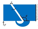
We had to constraint on the range of output frequency of the gearbox fo which we derived
Flapping frequency from Strouhal Number
St = fA/U
f- flapping frequency
A- Stroke Amplitude = 0.35 m (average for seagull)
U- Velocity = 3 m/s (general velocity for seagull)
St = 0.4
f= (St*u)/A
f= (0.4*3)/0.35
Flapping Frequency = 3.5 Hz
We set flapping range between (3-6.5 Hz)
Reference - Taylor, G., Nudds, R. & Thomas, A. Flying and swimming animals cruise at a Strouhal number tuned for high power efficiency. Nature 425, 707–711 (2003). https://doi.org/10.1038/nature02000
While we had the flapping frequency, it was important to set constraints on the ornithopter's dimensions. While performing a literature review, we found a paper titled "Comparative Scaling of Flapping- and Fixed-Wing Flyers" by Tianshu Liu, which found a very interesting relation between weight and the dimensions of birds and aircraft. This gave us a rough estimate of the design parameters. We paired these rough estimates with Park Hawk Model dimensions to set proper design parameters.

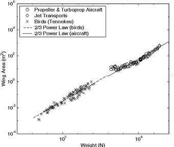
Wing Area vs Weight relation
We found that the observation of a Seagull with 0.4kg weight fit exactly with the formulated relation and we also compared it with the design parameters of Park Hawk Model.

From above relations and values we set our design parameters as follows:
-
Wing Span b = 1.042 m
-
Chord Length = 200 mm
-
Wing Area S = 0.2084 m²
-
Wing Loading (Upper Limit) = 5.120/0.2084 = 24.5681 N/m² (less than observed 25 N/m² range limit)
-
Aspect Ratio = 5.21
-
Wing Material - Rip Stop Nylon
-
Wing Structure - CF Pultrusion Rods
To generate the eliptical tip path of the wing, I decided to design and simulate a gearbox which could generate eliptical path. It was just a random arrow shot into darkness.

Iteration 1
The given iteration was scrapped as it didnt generate results as expected and Multi Body Dynamic approach suggested that the output didn't generate enough force. Also mounting was not rigid enough to hold up a 500mm long wing and the air resistance.
Replicated Park Hawk Model Gearbox to understand the force outputs using MBD Simulations. We scrapped this iteration because this consumed too much of body length and would have made it difficult to mount payload.

Iteration 2
We found out dual cranking gearbox to be simple, easy to mount, compact and enough for our application, so I designed the first iteration of gearbox, got it prototyped using FDM 3D printer & assembled. Major concern was shearing of 3D printer gear along the layers and lack of strength near the gear tooth due to less material deposition (module = 1) which I avoided upto a certain limit by changing the orientation of print in build envelope.

Iteration 3 CAD Model

Iteration 3 Prototype
We achieved a total gear reduction of 54.2:1 which gave ~400 rpm output with 100% throttle input by 1700KV BLDC motor (3S rated).
Major issues noticed:
-
Tolerance issue in the 3D prints, which can be considered in the design.
-
Design Error in Cranking Gear, it considered diameter of crankpin locus circle same as crank pitch circle diameter.
-
Fastening of Crank outputs needs to be improvised.
-
Crank pinion broke off (z = 10, m = 1, ID = 5mm) after a week of constant testing.
Now that the gearbox was prototyped, I focused on designing flaps using crank gear, based on the calculations made in kinematic sketchs above. I used M2 tie rod ends to create the connecting rod and used '+' shaped wing connectors (highlighted in red) to generate flaps. These connectors allow modular connection to wings.


Iteration 4 CAD Model

Iteration 4 Prototype
While we fixed the tolerance issues in the gearbox, gears' facewidth was not enough to widthstand the shear force. It also caused crank gears to go out of phase.
The frame designed to hold the wing connectors had 2 plates (supposed to be CF sheet but used 3D prints for prototype) and a pin which holds everything together. The cantilever mounting of motor caused jumping of pinion on variation in loading which didnt allow stable mechanical power input to the planetary gearbox.
Overall this design confirmed the cranking kinematics but it lacked frame rigidity. In the next iteration, we have to focus to reducing the jumping of bldc motor, increase thickness of cranking gears and focus on the frame rigidity.
We rectified the issues found in the previous iterations, it created a stable flapping motion now. To improvise the frame rigidity, I added 4 rigid links connecting both the vertical plates and printed them as a unibody frame.
Motor was directly connected to the input of planetary gearbox (though it reduced output torque, but according to our calculation, it is well above the required torque. This avoided the cantilever mounting of motor and stabilised motor power input.


Iteration 5 CAD Model
Somehow I had to reduce the noise caused by 3D printed planetary gearbox. :-/
Also i was lucky enough to have found vendors who sell nylon fasters and M1-M2 sized screws. This prototype was designed in 3 modules: (a) BLDC Motor Mount & Motor, (b) Planetary Gearbox and (c) Crank Gearbox which can be tested separately for work-life estimation.

After 5 Iterations, following variable values have been achieved at 45% throttle cuttoff:
-
Flapping = 3.3 Hz
-
Weight = 86 gm
-
Overall Gear Ratio = 37.08:1
-
Complete Polymer Assembly
Reference - Design & Construction of an Autonomous Ornithopter by Zachary J. Jackowski (https://dspace.mit.edu/handle/1721.1/52809)
(Pls ignore the title error)
Iteration 5 Prototype
For tail, we needed actuated roll and pitching of tail, for this kind of movement, one simple method was directly connecting tail to motor. In that case, COG would have shifted back so it was better to use some mechanism for tail. The most simple joint came to my mind was a ball socket joint which can be controlled using a pair of MG90 servo motors connected via connecting rods.


Tail Iteration 1
First iteration turned out to be partial success in pitching as it was unable to constraint the roll action. The flat plane couldn't create mutually perpendicular force vectors on the tail, resulting in unconstrainted tail roll.
To fix up the issues, we split the flat plane into two mutually perpendicular planes which generated mutually perpendicular forces, resulting in a better actuation.


Tail Iteration 2
Some CFD simulations were performed by Thomas to get the force (Y) vs pitch and force (Z) vs roll relation and also to see if the tail would withstand the loading.

Tail CFD Simulation at (a) Pitch = 0deg, (b) Pitch = +25deg, (c) Pitch = - 20deg
Our Design Parameters:
-
Wing Span b = 1.042 m
-
Chord Length = 200 mm
-
Wing Area S = 0.2084 m²
-
Wing Loading (Upper Limit) = 5.120/0.2084 = 24.5681 N/m² (less than observed 25 N/m² range limit)
-
Aspect Ratio = 5.21
-
Wing Material - Rip Stop Nylon
-
Wing Structure - CF Pultrusion Rods
While few ornithopters used flat aerofoil and other used standardised aerofoil curve, we decided to mimic the real seagull wing shape. We found out that the Root of Seagull wing has a general aerofoil curve which transitions into a flat aerofoil. I decided to replicate the same mechanically.
Based on the design parameters and expected flight velocity of 6-10 m/s, I decided to go with Selig S1223 standard aerofoil due to its ability to product high lift at low Reynolds number.
To mathematically support the decision, I performed a CFD simulation, which suggested enough lift generation of ~4.4 N (>0.4kg) lift at 6m/s air velocity and 10deg AOA. It also proves that at enough speed, the ornithopter can glide and save energy.
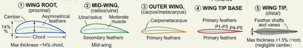
Cross Section Transition of a Seagull wing at various sections


CFD Simulation of Wing Aerofoil
To save on weight and utilise it in the payload, we decided to go with passive flapping where we found an interesting research paper by A A Wissa, et. al. dated 2012 titled "Passively Morphing Ornithopter Wings Constructed Using A Novel Compliant Spine: Design and Testing". The above research paper used a Delrin based compliant spline in Park Hawk Model which passively morphs and saves energy on upstroke thus increasing the efficiency of the flying operation.


Downstroke
Upstroke
Design, Placement and Behaviour (Deflection) of the Compliant Spine when externally loaded by the wings

(a) Power req. vs Freq. and (b) Freq. vs Throttle

(a) L/W vs Throttle and (b) Thrust vs Throttle
The above results from the paper were attractive enough to give us a solid base of further design. As our main aim behind taking up this project was learning research skills, we planned to go with TPU matl. Instead of Delrin which would have pushed us to change the design.
We recreated the design given in paper with TPU at 80% infill, unfortunately the material couldn't hold up the weight of end tip spars.

TPU Compliant Spine Iterations : (1) design based on research paper, (2) customised design
To constraint its deflection in upstroke, I came up with a parabolid shape constraints on the top plane to limit the extension of spring. This also improved torsional rigidity. While there was an improvement compared to previous iteration, it was still nowhere near comparable to Delrin spines and required more iterations with varying parameters (design and infill parameters) until we found the optimal.

Wing Prototype with Selig S1223 standard aerofoil and aeroelastic CF spars


Wing Structure and Wing Prototype In-Situ Testing
(These were performed without morphing as spines were still in iteration phase)
Now that we have a mechanically working structure, we had to validate our model output variables with those indicated by the simulations. It also included optimising certain elements like Compliant spines and the gear strength. Thomas took up the iterative tasks, I took up the task of designing control systems for attitude stabilisation and FPV setup and Pranav started with the testbed setup to record all the optimisation data for analysis.
Ornithopter produces many unbalanced forces which would affect the flight stability. In order to balace out these forces, an active control system needs to be deployed on the onboard microcontroller. The major control variables in the ornithopter would be freq. of wing motor and the state of two tail servo motors.
I refered to a research paper published in Chinese Journal of Aeronautics by Wenfu XU, et. al. titled "Flight control of a large-scale flapping-wing flying robotic bird: System development and flight experiment" which used a 6DOF multi body dynamic approach to generate a set of motion equations for flight stability. The paper implemented these equations on HIT ornithopter with ~2m wing span.
